
Manual J · Manual S · Manual D
Manual J → Manual S → Manual D: The Proper HVAC Design Sequence
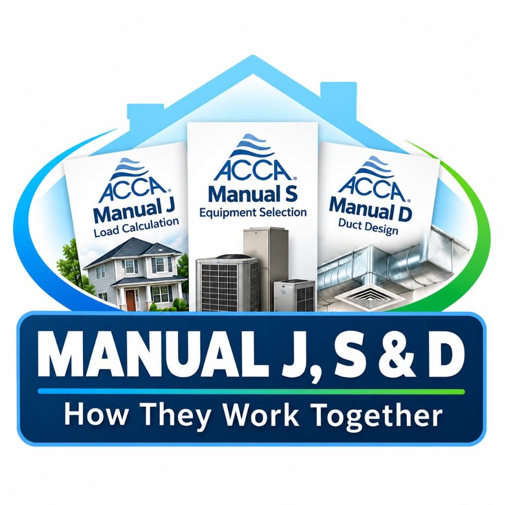
Residential HVAC design follows a logical sequence: calculate the heating and cooling loads, select equipment capable of meeting those loads, and design the duct system to distribute the required airflow. ACCA Manual J, Manual S, and Manual D provide the procedures for completing these connected tasks.
Why Sequence Matters
The order of residential HVAC design affects the information available at each stage.
Selecting equipment before calculating the loads may result in equipment that is unnecessarily large or unable to meet the home's design requirements.
Likewise, sizing ducts without knowing the selected equipment's airflow and blower performance can produce a duct system that does not match the equipment.
Manual J, Manual S, and Manual D establish a logical sequence while allowing necessary coordination and revisions between stages.
The objective is a design in which the building loads, equipment capabilities, and duct distribution system are compatible.
Step 1: Manual J Load Calculations
Manual J calculates the heating and cooling loads for the home and individual rooms.
The calculation considers building construction, insulation, windows, orientation, infiltration, and local design weather conditions.
Whole-house loads establish the heating and cooling requirements used for equipment selection.
Room-by-room loads provide the foundation for determining airflow distribution to individual spaces.
These results must reflect the actual proposed construction rather than assumptions based only on floor area.
Step 2: Manual S Equipment Selection
Manual S uses the Manual J loads to evaluate suitable heating and cooling equipment.
Equipment must be assessed using applicable manufacturer performance data, including capacity at the project's design conditions.
Nominal equipment tonnage does not necessarily represent its actual delivered heating or cooling capacity.
The selection process also considers applicable sensible and latent cooling performance and heating capacity.
The resulting equipment selection and operating characteristics provide important inputs for the duct design.
Step 3: Manual D Duct Design
Manual D uses the required airflow, selected equipment's blower performance, and proposed duct layout to calculate duct dimensions.
The procedure accounts for available static pressure, component losses, duct resistance, and total effective length.
Supply and return ducts must be evaluated as parts of the complete distribution system.
If the selected equipment or duct routing changes, the calculations may need to be revised.
The final design establishes calculated duct requirements, which can be used to guide installation.
Technical References
- ACCA — Manual J, Residential Load Calculation
- ACCA — Manual S, Residential Equipment Selection
- ACCA — Manual D, Residential Duct Systems
- ACCA — Bob's House: Understanding the Residential HVAC Design Process (publication reference)

About the Author, Tracy Savoy
Tracy Savoy, owner of Savoy Engineering Group, has worked in residential HVAC design since 2005. Her ACCA Manual J, S, and D training and Wrightsoft experience support her explanations of how load calculations, equipment selection, and duct design work together.
View Tracy's Training & Experience