
Manual J · Manual S · Manual D
The Complete Residential HVAC Design: Manual J, S, and D Case Study
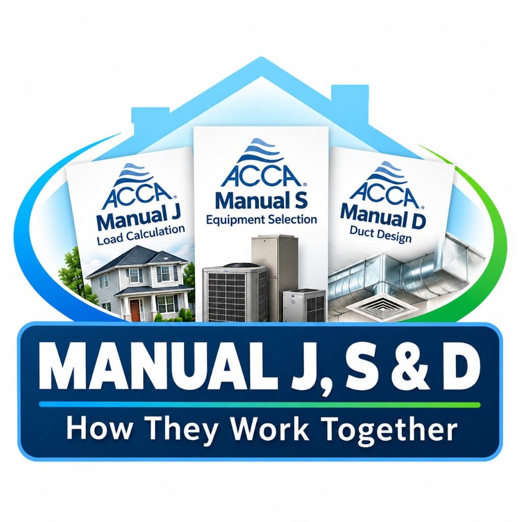
A coordinated residential HVAC design begins with the building's heating and cooling requirements, continues through equipment selection, and concludes with calculated duct distribution requirements. This hypothetical case study illustrates how ACCA Manual J, Manual S, and Manual D work together for a single-family home. It explains the process without representing the example as a completed project or providing fabricated calculation results.
About This Case Study
This educational example follows a hypothetical single-family residence through the residential HVAC design process.
The purpose is to demonstrate how building information, heating and cooling loads, equipment selection, and duct design are connected.
No actual project calculations or manufacturer equipment selections are presented.
A complete project would require verified building specifications, appropriate design conditions, manufacturer performance data, and a proposed duct layout.
The example illustrates the sequence and coordination of the calculations rather than establishing equipment sizes or duct dimensions for a particular home.
The Hypothetical Home
Consider a proposed single-family home with multiple bedrooms, a living area, kitchen, bathrooms, and other conditioned spaces.
The building plans identify room dimensions, ceiling heights, window locations, insulation specifications, and the proposed mechanical equipment location.
Additional information includes window performance, building orientation, and appropriate indoor and outdoor design conditions.
These details are necessary because different rooms experience different heating and cooling loads.
For example, rooms with greater window exposure or different construction characteristics may have different cooling requirements even when their floor areas are similar.
Step 1: Manual J Load Calculations
The first stage is to calculate the home's heating and cooling loads using ACCA Manual J.
The calculation evaluates the building characteristics and design conditions to determine whole-house and room-by-room requirements.
Whole-house heating and cooling loads establish the requirements used for equipment selection.
Room-by-room loads provide the foundation for determining how conditioned airflow should be distributed throughout the residence.
Cooling calculations also distinguish sensible and latent loads, which are important for evaluating equipment performance.
At this stage, the loads have been established, but no specific equipment model or duct dimensions have been selected.
Step 2: Manual S Equipment Selection
The next stage uses the Manual J results to evaluate heating and cooling equipment under ACCA Manual S.
Applicable manufacturer performance data is reviewed to determine whether the proposed equipment satisfies the calculated loads at the project's design conditions.
For cooling, the evaluation considers total and sensible capacity and applicable latent performance.
For heating, available capacity at the winter design conditions is evaluated, with supplemental heating considered where applicable.
The selected equipment's airflow requirements and blower performance also become important inputs for the duct design.
Equipment selection must satisfy applicable Manual S criteria rather than relying solely on nominal tonnage.
Step 3: Manual D Duct Design
The final stage uses the room airflow requirements, selected equipment's blower performance, and proposed duct layout to complete the Manual D calculations.
Supply and return duct dimensions are determined using available static pressure, duct resistance, and total effective length.
The design must account for pressure losses associated with applicable system components and duct fittings.
The calculated duct requirements are coordinated with the building layout and available installation space.
If equipment specifications or duct routing change, the design may need to be reviewed and revised.
The completed Manual J, Manual S, and Manual D calculations establish a coordinated design foundation. Actual performance depends on proper installation, testing, balancing, and field verification.
Technical References
- ACCA — Manual J
- ACCA — Manual S
- ACCA — Manual D
- ACCA — Bob's House: Understanding the Residential HVAC Design Process (bibliographic reference; no public URL available)
- U.S. Department of Energy — Building America Solution Center

About the Author, Tracy Savoy
Tracy Savoy provides residential Manual J, S, and D services nationwide through Load-Calculations.com. She draws on practical design experience to explain why construction information, selected equipment, and duct plans need to remain coordinated throughout a residential HVAC project.
View Tracy's Training & Experience